Imaging large samples (whole organs or tissue biopsies) faces the issue of light aberrations due to its interaction with the specimen. Biological samples are chemically and structurally heterogeneous, with different refractive indexes and optically dense areas, which makes it difficult for light to travel through. Although clearing techniques are becoming more efficient, they are still slow, labour-intensive and unsatisfactory for many purposes[1]. This significantly limits the potential of LSFM (Light Sheet Fluorescence Microscopy) as a tool for research, discovery and diagnosis. Common solutions are adding additional light sources, which decreases depth resolution, or mounting several detection pathways, which increases the price, maintenance needs and demands specialized reconstruction software. QLS-Scope makes use of its proprietary sample holding system and built-in software to provide a simpler, cheaper solution. Our ability to rotate the sample allows for 3 imaging modes that fit all sample quality possibilities, as the perfect sample positioning can always be achieved. To illustrate their application we have imaged a semi-cleared mouse heart with less-than-optimal optical features.
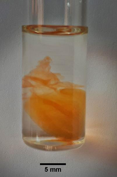
| Figure 1. Semi-cleared mouse heart, dimensions 8x12x6 mm (x, y, z) in an imaging glass tube. The RI of the material matches those of the clearing medium and the imaging chamber. |
MATERIALS AND METHODS
Prior to clearing, the sample was stained with CYBER-Green™ to obtain a homogeneous fluorescent signal. Sample clarification (based on ethyl-cinnamate) was left incomplete to produce a specimen with colour and optically dense areas (Figure 1). The sample was introduced in a glass tube of appropriate diameter and mounted in the QLS-Scope sample holder, which was then automatically placed into a cuvette with a liquid of matching refractive index (1.52). The sample was imaged using a 488 nm laser, a 531(40) BP filter and a 1x/NA0.025 air objective under the following conditions:
SPIM: 500 sections at 12.5 micron steps. Exposure time= 80 ms. Laser power=75 mW. Total scan time= 50 seconds.
2-angle SPIM: 2 series of 500 sections at 12.5 micron steps, taken at 0º and 180º by rotating the sample after each series. Exposure time= 80 ms. Laser power=75 mW. Total scan time= 115 seconds. The images were then combined using the built-in Merge-SPOT function, exported to ImageJ[2] and resliced using the default parameters.
SPIM-OPT: 20 consecutive sections at 300 microns steps were taken and summarized in a single maximum intensity projection. The process was automatically iterated 500 times at 0.7º increments. Exposure time= 50 ms. Laser power= 60 mW. Total scan time= 27 minutes. The images were then combined using the built-in i-RADON function, exported to ImageJ and resliced using the default parameters.
ImageJ was used to process the images and perform 3D reconstructions. The same brightness/contrast settings were applied to all datasets for presentation.
RESULTS
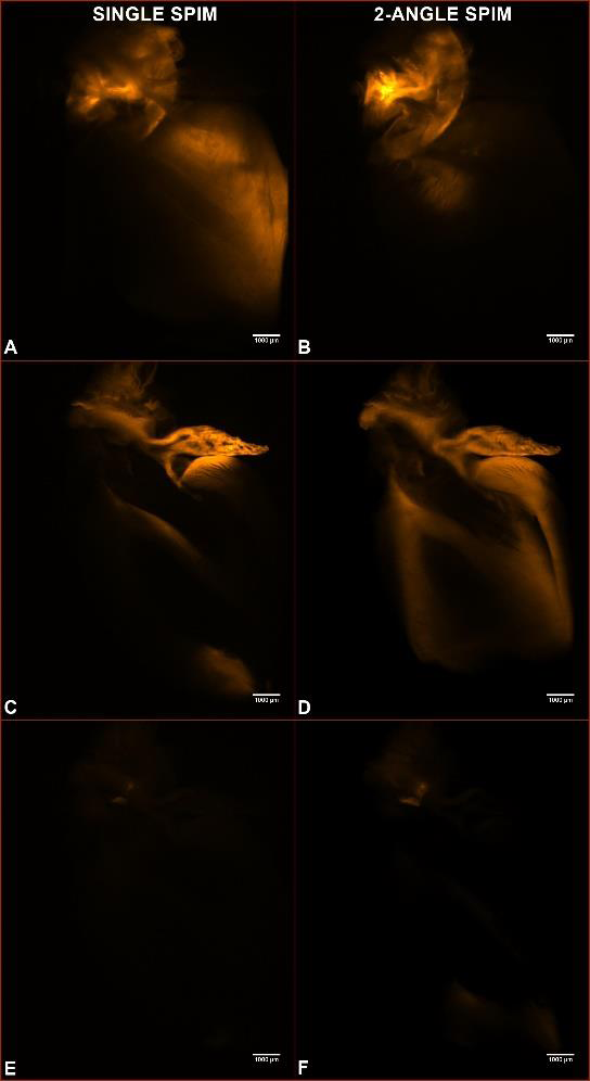
| Figure 2. Captures of a SPIM series (panels A, C, D) and a 2-angle SPIM series (panels B, D, F) through the sample shown in figure 1 (500 sections at 12.5 micron steps). A and B are collected 1.25 mm into the sample; C and D, 4 mm; E and F, 5.7 mm. |
IMAGE QUALITY COMPARISON BETWEEN SINGLE AND 2-ANGLE IMAGING MODES
The semi-cleared state of the sample presented a hindrance for light penetration, resulting in poorer resolution at the far end. This can be readily observed in Figure 2, where single and 2-angle SPIM acquisitions are compared. Not much difference in image quality is evident in the initial Z-slices (A, B panels), but as the scanning enters the sample, less light is able to reach the detector, which limits the amount of information available by single SPIM (panels C and E, where only the brightest parts of the sample are visible). The ability to collect information from 2 angles and reconstruct a single set of images allows to get increased detail and resolution from the whole sample volume (panels D and F). QLS-Scope implements this feature (Merge-SPOT) within its standard software, without the need for additional optics and with a negligible increase in exposure time, thus protecting the sample from photo bleaching.
IMPROVED 3D RECONSTRUCTION WITH SPIM-OPT
QLS-Scope incorporates SPIM-OPT, an imaging mode that collects 360º optical data by gradually rotating the sample and performing a fast SPIM scan at each position. The software reconstructs the different angular views into a single dataset with isotropic resolution (using the built-in i-RADON tool), as the whole volume of the sample has been scanned from the best optical view point (in front of the objective).
This feature is critical to obtain representative 3D reconstructions from the data. Figure 3 compares such models obtained from a single SPIM, 2-angle SPIM and 500 angle SPIM-OPT. The upper row shows the backside (from the objective´s position in a SPIM) of a surface render based on the data obtained by single SPIM, 2-angle SPIM and 500-angle SPIM-OPT. In the first panel (single SPIM) the render is incomplete due to lack of information from that area. Integrating optical data from additional angles increases the image quality. Note the increased range of colour depth in the 500-angle reconstruction, indicative of a greater resolution. The SPIM-OPT render has no void areas, as imaging from all angles can extract optical data even from sub-optimal samples. The lower row shows orthogonal views calculated from the same datasets. Again, the combination and reconstruction from several angles dramatically increases the Z-resolution and quality.
The simplicity and high scanning speed of QLS-Scope facilitates choosing and applying the most adequate imaging mode (single SPIM, multiple SPIM or SPIM-OPT) for each sample.
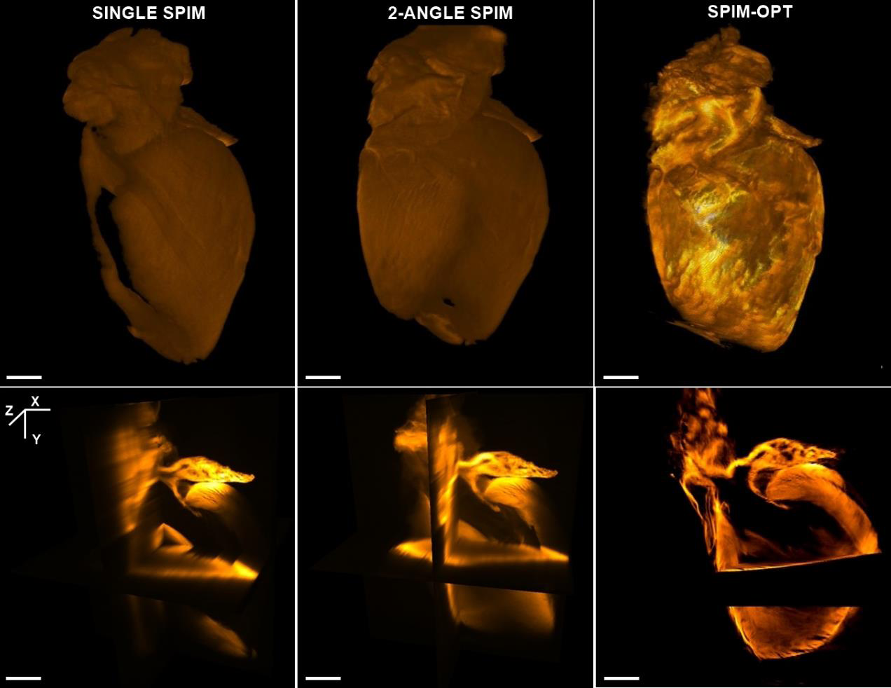
| Figure 3. 3D renders from single SPIM, 2-angle SPIM and SPIM-OPT data sets (left, centre and right panels, respectively). The upper row shows a surface map of the sample modelled from each imaging mode. The lower row shows an orthogonal view of the sample using the different modes. Note the increased resolution and definition of the models as the software incorporates additional angles to the reconstruction, to the point of filling voids in the single SPIM images. Scale bars are 1 mm. |
ACKNOWLEDGEMENTS
We wish to thank Dr. Maria José Coronado at the University Hospital Puerta de Hierro, Madrid (Spain) for her collaboration in the clearing of the sample.
[1] Matryba, P.; Kaczmarek, L. and Goła˛ J. July 2019. Advances in Ex Situ Tissue Optical Clearing. Laser Photonics Rev.
[2] Schindelin, J.; Arganda-Carreras, I. & Frise, E. et al. (2012), “Fiji: an open-source platform for biological-image analysis”, Nature methods 9(7): 676-682.
Application Note
Luis Muñiz, PhD
Nikos Ekizoglou, PhD
Prof. Jorge Ripoll
PlaneLight SL
December 2019